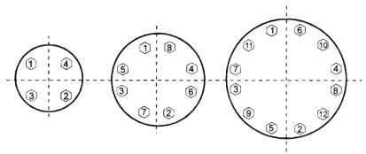
Proper installation of a flange can be made easier with the help of installation data. The following includes important points, a torque sequence chart and a bolt information table.
Important Notes
- Recommended Gaskets: full face, 1/8" thick elastomeric, 50-70 Shore A hardness.
- Bolt threads should be well lubricated.
- Nut and bolt threads should be free running during assembly.
- Follow illustrated bolt tightening sequence.
- Always use full size flat washers with bolts and nuts.
Torque Sequence Chart

Bolt Information Table
| Size | Bolt Circle Diameter |
Bolts Required |
Bolt Size (UNC x Length) |
Torque |
| ½ | 2.37 | 4 | ½-13 x1 ¾ | 15-20 |
| ¾ | 2.75 | 4 | ½-13 x 1 15/16 | 15-20 |
| 1 | 3.12 | 4 | ½-13 x 2 | 15-20 |
| 1¼ | 3.50 | 4 | ½-13 x 2 ¼ | 15-20 |
| 1½ | 3.87 | 4 | ½-13 x 2¾ | 15-20 |
| 2 | 4.75 | 4 | 5/8-11 x 3 | 20-30 |
| 2½ | 5.50 | 4 | 5/8-11 x 3¼ | 20-30 |
| 3 | 6.00 | 4 | 5/8-11 x 3 5/8 | 20-30 |
| 4 | 7.50 | 8 | 5/8-11 x 3¾ | 20-30 |
| 5 | 8.50 | 8 | ¾-10 x 6-3¾ | 25-35 |
| 6 | 9.50 | 8 | ¾-10 x 4 3/8 | 30-50 |
| 8 | 11.75 | 8 | ¾-10 x 4 3/8 | 30-50 |
| 10 | 14.25 | 12 | 7/8-9 x 4½ | 53-75 |
| 12 | 17.00 | 12 | 7/8-9 x 4 5/8 | 53-75 |
Note: UNC=Unified National Course. Mating dimensions and configurations conform to ANSI B 16.5, Class 150 flanges. Socket diameters conform to ASTM D 2467. Working Pressure is 150 psi water at 73.4°F. Use primer and heavy-bodied PVC cement in accordance with ASTM D 2855.
